#Industry News
Ergonomic points of control lever design
The ergonomic key points of the design of marine handles need to be closely combined with the special working conditions of ship operations, such as long working hours, high vibration, wet and slippery environments, etc. The core objectives are to improve handling comfort, reduce fatigue and ensure precise control.
I. Adaptation of Handle Shape and Size
1. Matching of Hand Size
(1)Diameter: According to the size of the human palm (the average palm width of adult males is about 90-105mm, and that of adult females is about 80-95mm), the diameter of the handle is recommended to be controlled within 30-50mm:
①Fine operation handle (such as course trimming): 30-40mm (convenient for single-handed grip and flexible rotation);
②Force type handle (such as windlass, mooring winch): 40-50mm (increases the contact area and distributes the grip force).
(2)Length: The effective gripping length of the handle needs to cover from the thenar eminence of the palm to the root of the middle finger, usually 120-150mm. Avoid being too short, which may lead to unstable gripping, or too long, which may increase the burden on the wrist.
2. Design of Grip Shape
(1)Bionic Arc: It conforms to the natural bending shape of the palm. For example, the back of the handle is raised (in line with the arc of the hypothenar muscle), and the finger groove is designed (to fit the force application points of the index finger and thumb), reducing the pressure on the palm center (sweating and slipping are likely to occur during long-term operation).
(2)Anti-slip Texture: The surface adopts knurling, rubber molding, or soft coating (Shore hardness 60-70A). The depth of the texture is 0.5-1mm, and the wet friction coefficient is ≥0.6 (GB/T 20295 standard), improving the gripping stability in wet environments.
-------------------------------------------------------------------------
II. Optimization of Operating Force and Stroke
1. Design of Operating Force Threshold
(1)Static Grip Force: The recommended continuous operating force of a single hand is ≤30% of the maximum grip force (the average maximum grip force of adult males is about 400-500N, and that of adult females is about 250-350N), and avoid exceeding 150N (to prevent forearm muscle fatigue).
(2)Dynamic Torque:
①Rudder Wheel/Telegraph Handle: The steering/pushing and pulling torque ≤50N·m (the recommended value of ISO 6846), and it is equipped with a damper to provide uniform resistance feedback to avoid misoperation caused by sudden jamming;
②Emergency Handle: The triggering force needs to be clearly distinguished from regular operations (for example, the combined force of "pressing + lifting" of the lifeboat release handle ≥80N to prevent accidental touch).
2. Matching of Stroke and Precision
(1)Fine-tuning Handle (such as radar gain adjustment): The stroke ≤20mm, and it is combined with gears/potentiometers to achieve precision control at the 0.5° level;
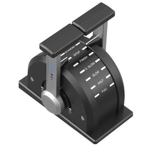
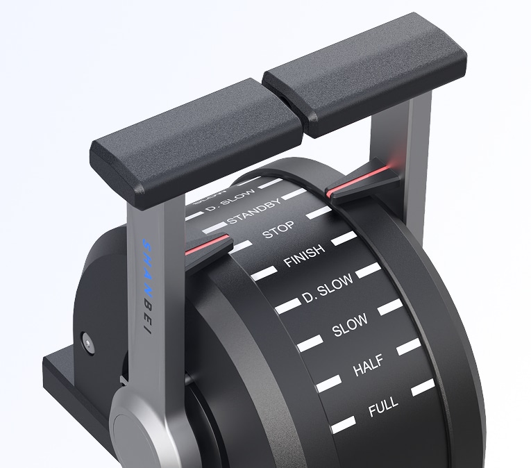
(2)Coarse-tuning Handle (such as windlass start and stop): The stroke is 50-100mm. The gear nodes (such as the three gears of "neutral-low speed-high speed") are clearly defined through the limit device, and a "click" tactile feedback is accompanied during operation.
-------------------------------------------------------------------------
III. Adaptation of Operating Position and Posture
1. Installation Height and Angle
(1)Seated Operation in the Cockpit: The height of the handle center from the seat surface is 600-700mm (referring to the seated operation height standard of GB/T 14774), and the angle between the handle axis and the horizontal plane is 15°-30° (the natural neutral position of the wrist, reducing the ulnar deviation/radius deviation angle).
(2)Standing Operation on the Deck: The height of the handle is 900-1100mm (to adapt to crew members of different heights, and the base can be adjusted by ±100mm), and the inclination angle is 20°-45° (convenient for looking down to observe the handle position and equipment status).
2. Optimization of the Force Application Direction
(1)Horizontal Push-pull Handle (such as telegraph): The operation track is parallel to the sagittal plane of the human body, avoiding excessive lateral extension of the arm (the maximum operation range ≤400mm, and the body needs to be moved if it exceeds this range);
(2)Vertical Pull Handle (such as fire valve): The pulling force direction is consistent with the axis of the forearm, and the center of gravity of the handle is close to the center of the palm, reducing the compensatory force exerted by the shoulder.
-------------------------------------------------------------------------
IV. Operation Feedback and Comfort
1. Multimodal Feedback Design
(1)Tactile Feedback: Vibration motor (such as low-frequency vibration at 50Hz when overloaded), damping step feeling (a sudden change in resistance of 0.3-0.5N·m during gear shifting);
(2)Visual Feedback: An LED indicator is integrated at the tail of the handle (green = normal, red = fault, blue = standby), and the colors comply with the safety color standard of ISO 3864;
(3)Auditory Feedback: A crisp prompt sound (30-60dB) is accompanied during operation, which is distinguishable from the environmental noise (usually ≤85dB in the cockpit).
2. Design for Reducing Fatigue
(1)Weight Balance: The self-weight of the handle ≤500g (for handles of mobile devices), and for fixed handles, bearings/balance weights are used to reduce the inertia force during operation;
(2)Palm Pressure Relief: A hollow area of 10-15mm is reserved in the middle of the handle (to avoid numbness caused by long-term pressure on the palm center), and the arc transition at the thenar eminence (R≥15mm) reduces soft tissue friction.
-------------------------------------------------------------------------
V. Adaptation to Special Scenarios
1. Operation in Wet/Slippery Conditions or with Gloves
The spacing of the handle surface texture ≥2mm (to prevent the retention of seawater/oil stains). The diameter of the handle suitable for wearing gloves is increased by 5-10mm, and the depth of the finger groove is deepened to 2mm to ensure precise operation when wearing cold-proof/anti-slip gloves (with a thickness of 3-5mm).
2. Emergency Operation Response
The emergency handle adopts a "large size + eye-catching red color scheme" (diameter ≥60mm), and the operation mode is simplified to a single-step trigger (such as a push-down emergency stop button, with a stroke ≤15mm and a triggering force ≤50N), and it is positioned within the range of ±200mm of the horizontal line of sight (meeting the need for quick positioning).
-------------------------------------------------------------------------
VI. Group Differences and Customization
1. Adaptation to Human Body Size Differences
For different crew groups of different ship types (for example, most of the crew on ocean-going cargo ships are male, and yacht operators may include females), adjustable handles (length ±20mm, angle ±10°) are provided, or handles are designed in different models (S/M/L sizes).
Referring to "GB/T 10000-1988 Dimensions of Chinese Adults", the key dimensions of the handle cover the adaptation range from the 5th percentile female to the 95th percentile male.
2. Compatibility with Operation Habits
Ambidextrous Design: Symmetrical handles (such as the rudder wheel without directionality), or handle bases that can be switched for left and right installation (such as the crane handle that supports left and right interchange) to meet the needs of left-handed operators.
-------------------------------------------------------------------------
VII. Standards and Testing Verification
1. Compliance with International Standards
ISO 6846 "Ergonomic Requirements for Ship Manoeuvring Devices": Specifies the safety thresholds for handle operation force, stroke, and position;
ISO 11226 "Ergonomics - Operation Force": Guides the design limits of static/dynamic operation forces.
2. Usability Testing
Simulate the bumpy environment of the ship (vibration frequency 1-20Hz, acceleration ≤2m/s²) to test the gripping stability of the handle;
Carry out a 4-hour continuous operation fatigue experiment, monitor the electromyogram signal (EMG) and subjective fatigue degree (RPE scale), and optimize the weight and grip feeling of the handle.
-------------------------------------------------------------------------
Conclusion
The ergonomic design of marine handles needs to take the coordination of "human-machine-environment" as the core. Through size adaptation, force sense optimization, feedback enhancement, and scenario customization, the goals of "precise operation, comfortable durability, and safety and reliability" are achieved in harsh marine environments. The key is to deeply integrate the physiological characteristics of the crew with the engineering design parameters in combination with the actual operation pain points of the crew (such as wet and slippery conditions, vibration, long working hours), and ultimately improve the efficiency and safety of ship operation.