#Product Trends
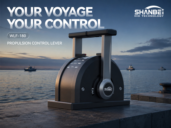
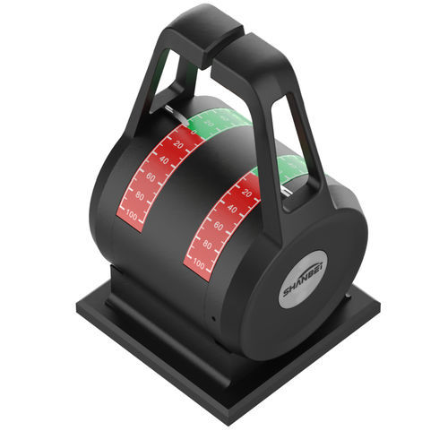
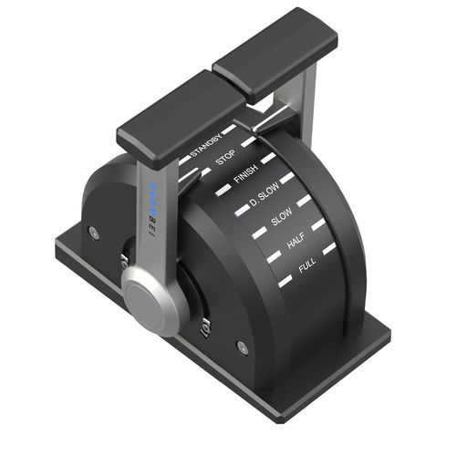
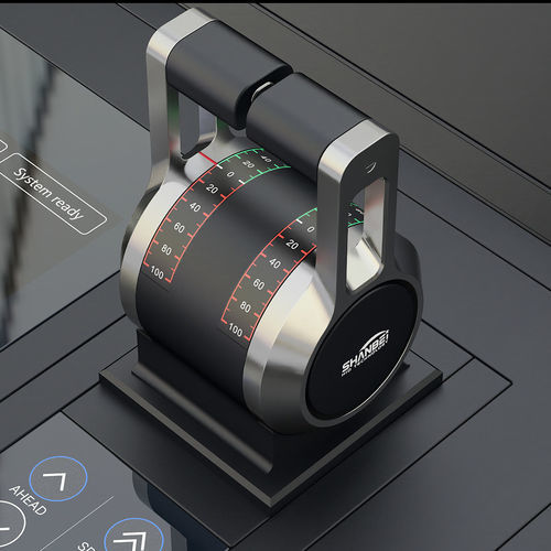
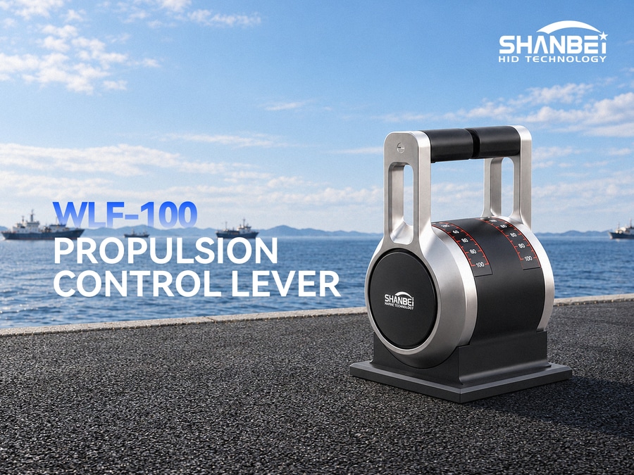
Propulsion Control Lever Integration Notes: Signal Matching Observations with Mainstream Propulsion System Controllers
After a propulsion control lever is installed into a console, the integration stage determines the commissioning cycle. The following are key points for signal matching.
I. Analog Output
1. 4-20 mA: A common analog interface, supported by most propulsion controllers, and can be connected directly.
2. 0-24 V: Suitable for the analog input specifications of some controllers. If the target system input range differs, compatibility can be achieved through voltage division or a signal conditioning module.
3. Direct 5 kΩ potentiometer output: A passive solution, suitable for refits of older vessels. As long as the resistance value matches, no parameter changes are needed on the controller side.
II. CAN Bus
1. The lever supports CAN output.
2. Common propulsion control systems use CAN architecture.
3. During integration, align the baud rate, message identifier, and data format.
4. Protocol specifications should be confirmed at the procurement stage; post-factory modification is inconvenient.
III. Redundant Signals and Volt-Free Switches
1. The terminal block usually defines potentiometer output and 4-20 mA output separately, providing dual-channel position feedback.
2. The ahead/astern volt-free switch is independent of the analog signal and is used for direction confirmation.
3. Power and signal wiring are separated, facilitating redundant configuration.
IV. Customized Interface Options
1. The operating range is commonly ±60°, with customizable 0~60° and -15~60° options to match the original system travel and eliminate recalibration.
2. Detent feedback options include neutral only, three detents, or feedback at each detent. On older systems with mechanical governors, detent feedback can replace some analog functions.
V. Pre-Integration Checklist
1. Signal type: Does the controller accept 4-20 mA, 0-24 V, or CAN? Prefer the native interface.
2. Terminal definitions: Match the lever terminals one by one with the controller I/O point list.
3. Protocol specifications: Confirm the CAN baud rate and message format at the procurement stage.
4. Redundancy scheme: When the controller supports dual-channel feedback, both potentiometer output and 4-20 mA output can be used simultaneously; the ahead/astern volt-free switch serves as direction redundancy.