#Industry News
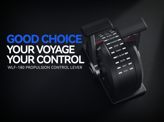
Scale Light Follow-up Function for Main Engine Control Propulsion Lever
As the lever rotates, the scale lights on the panel illuminate synchronously with the actual angular position of the lever, accurately indicating the current gear position.
I. Operating Principle
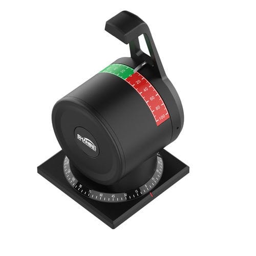
1)An angular position sensor (e.g., a potentiometer) inside the lever continuously detects the rotation angle and transmits the signal to the control circuit. Based on preset gear position thresholds, the control circuit drives the LED light at the corresponding scale position to illuminate.
---------------------------
II. Main Functions
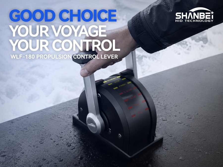
1)Provides the operator with immediate visual feedback, avoiding potential reading errors that may arise from relying solely on the mechanical pointer.
2)Enables clear identification of the current gear position in low-light engine room environments or under restricted viewing angles.
3)Forms a redundant indication together with the mechanical pointer, thereby improving system reliability and safety.
---------------------------
III. Typical Behavior
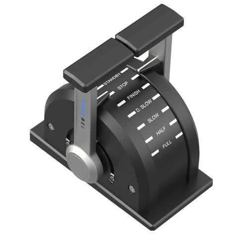
1)When the lever is pushed forward from the Stop position: The yellow Stop light turns off, and the green Ahead lights (Ahead 1 → Ahead 2 → Ahead 3 → Ahead 4) illuminate sequentially as the angle increases.
2)When the lever is pulled backward from the Stop position: The yellow Stop light turns off, and the red Astern lights (Astern 1 → Astern 2 → Astern 3 → Astern 4) illuminate sequentially as the angle increases.
3)When the lever returns to the Stop position, only the yellow Stop light illuminates; all other lights turn off.
---------------------------
IV. Additional Note
1)If during operation the mechanical pointer position is found to be inconsistent with the gear position indicated by the scale lights, a secondary calibration function can be used to re‑match them, ensuring accurate follow‑up indication.